I was provided the datasheet for the Automotive fully integrated H-bridge motor driver (VNH2SP30-E).
The assignment is to design and develop a PWM module. It has to provide three output signals:
INA (Pin 5)andINB (Pin 11)which provide the directionPWM (Pin 8). The pins are provided by Table 3 (and the .csv in our case).
The implementation follows Table 12 from the datasheet.
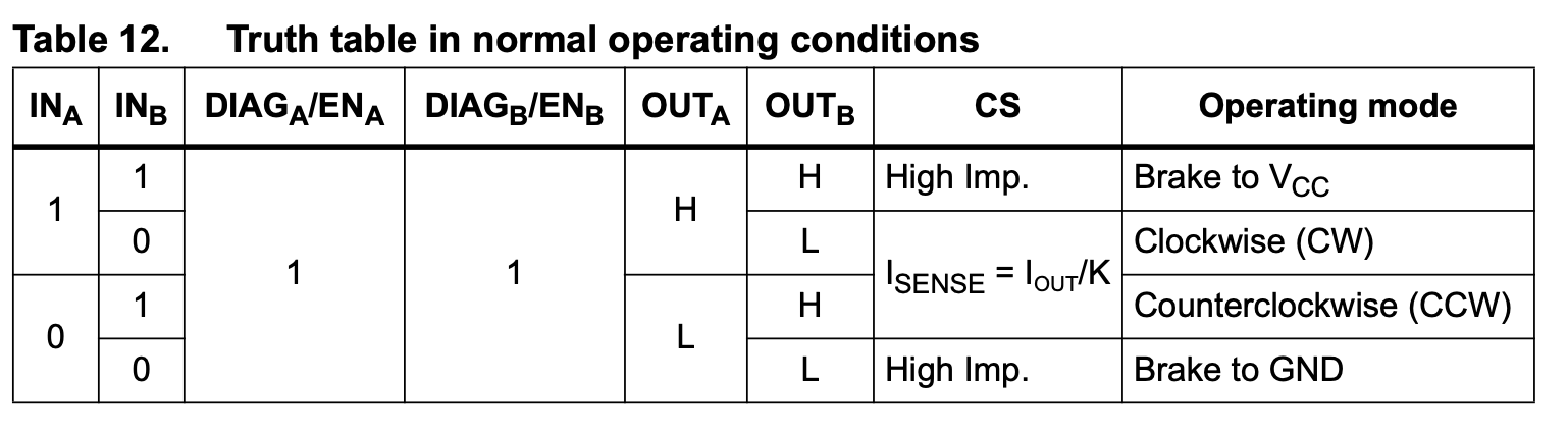
So for forward: INA=1, INB=0. For backward: INA=0, INB=1.
Design choices
- Maximum PWM frequency: (Table 9) — 20 kHz is actually the maximum, not the minimum ⇒ I use exactly 20kHz. At 50 MHz clock this gives .
- Minimum PWM off time: 6 µs (Table 9, footnote) — the PWM signal must stay low for at least 6 per cycle to avoid false short-circuit detection ⇒
- Logic input thresholds (Table 7): FPGA outputs 3.3V which satisfies the 3.25V high threshold from Table 7
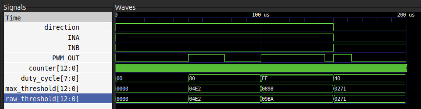
The duty cycle input is 8-bit (0–255). The raw PWM high-time in clock cycles is:
raw_threshold = (duty_cycle * PERIOD) / 256At duty_cycle = 255, this gives 2490 cycles high out of 2500 — leaving only 10 cycles () low, which violates the 6 µs minimum off-time required by the documentation. We also saw ourselves that a full 180 degree rotation results in 2490 on the encoder readings (at least on the yaw). To fix this, raw_threshold is capped:
max_threshold = min(raw_threshold, PERIOD - MIN_OFF_CYCLES) = min(raw_threshold, 2200)This guarantees PWM_OUT is always low for at least 300 cycles (6 ) at the end of every period, regardless of duty cycle.
The main loop
base[2] = (1 << 31) | (direction << 8) | duty;Writing to base[2] means writing to Avalon address 0x02 (third 32-bit word). This hits the write case in esl_bus_demo.v. The 32-bit value is packed as:
bit 31     = 1         -> cnt_enable = 1 (motor running)
bit 8      = direction -> 1=CW, 0=CCW
bits [7:0] = duty      -> 0-255 duty cycle
Reading base[0] and base[1] hits the read case in esl_bus_demo.v and returns the current encoder counts as signed 32-bit integers.
int32_t yaw   = (int32_t) base[0]; // read slave_address 0x00 -> yaw_count
int32_t pitch = (int32_t) base[1]; // read slave_address 0x01 -> pitch_count