1. ATTITUDE FROM THE GRAVITY VECTOR
Context:
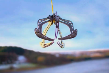
Consider that there is an IMU mounted on the claw.
Attitude from the gravity vector: Approximating the attitude of the claw by using the gravity vector. We know which way is up, and which is down.
- Consider a drone that is flying and experiencing rotations. The drone has a claw that hangs from a cord and swings with 3 rotational DoF.
- The drone has an IMU and the palm of the claw is equipped with an IMU as well.
- Question: What is the attitude of the claw, relative to the drone?
- The attitude can be estimated by using the gravity vector
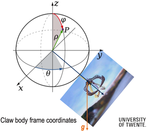
- Calculate a relative position, assume that the string is non-elastic (3 rotational DOF, of which yaw and pitch are the relevant ones, if we assume the gripper is symmetric w.r.t. Roll angle)
Solution:
So we have the following setup:
- A claw hangs from a drone on a cord with 3 rotational degrees of freedom
- IMUs on both the drone and claw measure acceleration
- The claw’s attitude (orientation) relative to the drone needs to be determined
So we know the gripper is symmetric w.r.t. Roll angle and the string is non-elastic. This makes it much easier as we only need the drone’s IMU.
What we need to do is calculate the angle between the IMU’s z-axis and the gravity vector using the accelerometer readings.
- The z-axis is simply , so the dot product is just .
- The magnitude of gravity is
In the end, the angle between the IMU’s z-axis and the gravity vector is:
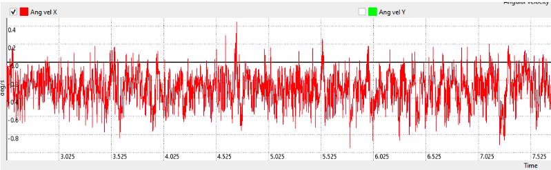
Can we measure the angular velocities of the claw?
Yes, but only if the claw IMU is on the center of rotation.
Why: An IMU measures angular velocity using its gyroscope. However, if the IMU is offset from the center of rotation, the accelerometer will also pick up centripetal acceleration from the rotation, which results in big drift. When the IMU is at the center of rotation, there’s no linear acceleration due to rotation — only pure angular velocity is measured by the gyroscope, giving you clean angular velocity data.
2. Where to mount the IMU on an autonomous car?
A) On the roof - Used for sensor fusion with GNSS (GPS)
B) Rear wheel axis - Benefits:
- No acceleration along the rear wheel axis (assuming no wheel slip)
- Can omit one accelerometer axis bias
- Simplifies to a point-like robot model for yaw angle
- Angular velocity comes from road inclination in the velocity direction
C) Center of mass - Sounds intuitive but offers no advantages
D) Anywhere - Funnily enough, this actually works
The idea is that the placement doesn’t affect rotation measurements. Angular velocity and forces transform the same regardless of location:
However, the acceleration at the body frame origin does depend on IMU position:
- This depends on the IMU position vector and angular acceleration .
3. IMU-to-Body Frame Transformations
Consider an autonomous car driving on a road. We define a car body frame B
- Origin OB: center of the rear-wheel axis.
- x-axis: forward along the car's longitudinal axis
- y-axis: to the left of the car
- z-axis: upwards, completing a right-handed frame
An IMU is mounted somewhere inside the car, at an arbitrary orientation and position.
Part 1: Single IMU on the Car
Context: The IMU has its own sensor frame S. The rigid-body relationship between S and the car body frame B is known from calibration:
- Rotation from IMU frame to body frame: (rotates vectors from S to B)
- Position of the IMU origin in the body frame: (vector from OB to the IMU)
At time , the IMU measures the angular rate and specific force, expressed in S:
(a) Transforming to the car body frame
Question: Write the expressions for and in the car body frame B, in terms of and .
Solution:
Since we know the IMU measures and each , then we covered earlier that we can go from the IMU sensor frame S to the car’s body frame B by simply applying the rotation matrix
Thus, the solution is:
Question: Explain in one or two sentences why it is important for vehicle state estimation (e.g. Kalman Filter) to express these quantities in the car body frame B rather than in the IMU frame S.
My response: In vehicle state estimation we usually talk about kinematics — and the kinematics we want to model is of the car’s. Since the car is our reference frame in this case, it makes perfect sense to transform everything into car body frame B and it further helps with sensor fusioning.
From professor: Using IMU-frame quantities directly would introduce frame-dependent biases and incorrect coupling between states.
(b) From specific force at the IMU to acceleration at the rear-axle
Context: Let the body have body-frame angular velocity , angular acceleration , and linear acceleration of the rear axle origin , all expressed in B.
Let the car’s orientation in the world be and let gravity in the world frame be
- =
The rigid-body relation for the acceleration at the IMU origin (expressed in B) is:
Moreover, the IMU accelerometer measures specific force:
Question: Show that the specific force in the body frame is
Solution:
We know that
So, naturally:
And we know that Rotation Matrices are orthogonal, so . And since :
Question: Use the rigid-body relation to derive an expression for the acceleration of the rear-axle center in the body frame (you may assume and are known from other sensors or from numerical differentiation of the gyroscope data):
Solution:
We know that , and therefore, and the follow:
So, in conclusion:
Part 2: Two arbitrarily aligned IMUs on the same car
Context: Now suppose there are two IMUs, with frames S and S, each with known and . For each IMU , the relations from Part 1 hold with the corresponding index.
Question: Write the body-frame specific force for each IMU:
Subtract the two equations to extract
Assume a planar car motion so that
and define . Compute and , and show that the x and y components of yield two scalar equations involving and
Solution:
I need to use the cross product. Here I covered that to compute the cross product between two vectors v and w, we do
And so, we calculate
Therefore, the x and y components are two scalar eq. involving and .
Part 3: Attitude Update Using Rodrigues’ Formula
Context: Rodrigues’ formula provides a closed-form, minimal-parameter, numerically stable way to update orientation from an angular velocity vector without using quaternions or integrating differential equations. Let be an estimate of the body-frame angular velocity, obtained e.g. from the IMUs.
We define
- The single-axis pair rotation
- The rotation magnitude
- The skew-symmetric matrix
The exact attitude is
Question: Using Rodrigues’ Rotation Formula, show that
Solution: To show this, we need to use lie algebra to go from SO(3) to . I covered this whole explanation in Mechanization.
For any matrix , the exponential is defined by
When , its powers satisfy
Starting from
use
Odd powers are proportional to :
Even powers are proportional to :
Using these identities, the series can be summed in closed form:
q.e.d.
Question: Using the Taylor expansions for and , derive the second-order small-angle approximation
Solution:
The second-order Taylor expansions for and are:
- AND after we neglect the higher-order terms we remain with
- AND after we neglect the higher-order terms we remain with
Which translates into:
Therefore, we derive the second-order small-angle approximation:
q.e.d.
Question: Let , rad/s, s.
Compute(numerically):
- ,
- and
Solution:
- . We can, of course, approximate and so we end up with a rotation around the z-axis of about which is a very small angle and the second-order approximation makes sense in this case.