Lecture from the RPCN course. Motivation: How does a stabilizer work?
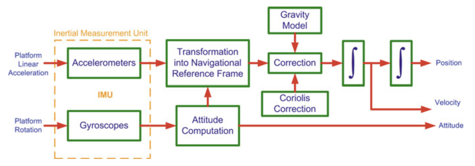
Mechanization is the process of converting the output of an IMU into position, velocity and attitude information. The outputs include rotation rates about three body axes measured by the gyroscopes triad and three specific forces along the body axes measured by the accelerometer triad, all of which are with respect to the inertial frame. Mechanization is a recursive process that starts with a specified set of initial values and iterates on the output.
Properties of angular velocities:
- We usually write which means the angular velocity of frame m, relative to frame k, expressed in frame p coordinates.
- For example, if we have a robotic arm with the fixed base-frame (k), the moving end-effector (m), and we want to express it in p frame coordinates: The angular velocity describes how fast m is rotating relative to k, but you can write those rotation rates using any coordinate system p.
- (chain rule)
- m rotates relative to h
- h rotates relative to k
- Therefore, m rotates relative to k
- All expressed in p-frame coordinates
I covered in Coordinate Systems that is the specific force of the IMU measured in body frame and that is the skew-symmetric matrix which represents the cross product as a matrix multiplication.
INS Mechanization in an Inertial Frame of Reference
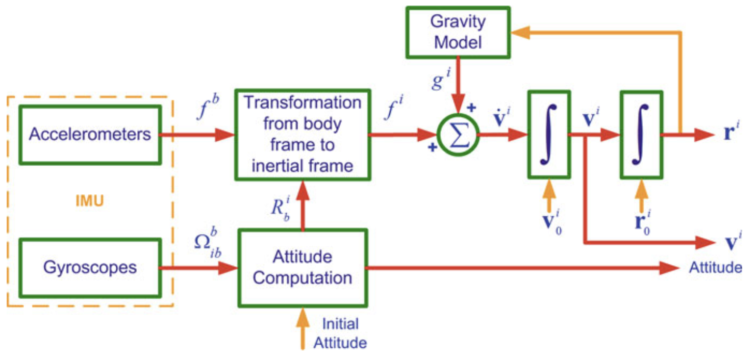
In the figure above we can see the mechanization of an INS(Inertial Navigation System) in the inertial frame. We want to integrate , , and from the IMU measured accelerations and angular velocities .
We know that
By letting , this can be rewritten as:
And for ease of solution, the set of three second-order differential equations can be transformed to a set of first-order differential equations as follows:
The measurements are usually made in the body frame, w.r.t. inertial frame. We can use the rotation matrix to extract
Since the gravitational vector is usually expressed in either the e-frame or the l-frame, it can be transformed to the i-frame through a rotation matrix or . We’ll consider e-frame
Substituting in the first-order differential equations, we get:
As discussed in Rotation Matrix Time Derivative, the rate of change of a transformation matrix is
The mechanization equations for the i-frame can therefore be summarized as:
These all use the measurement from the IMU.
INS Mechanization in ECEF Frame
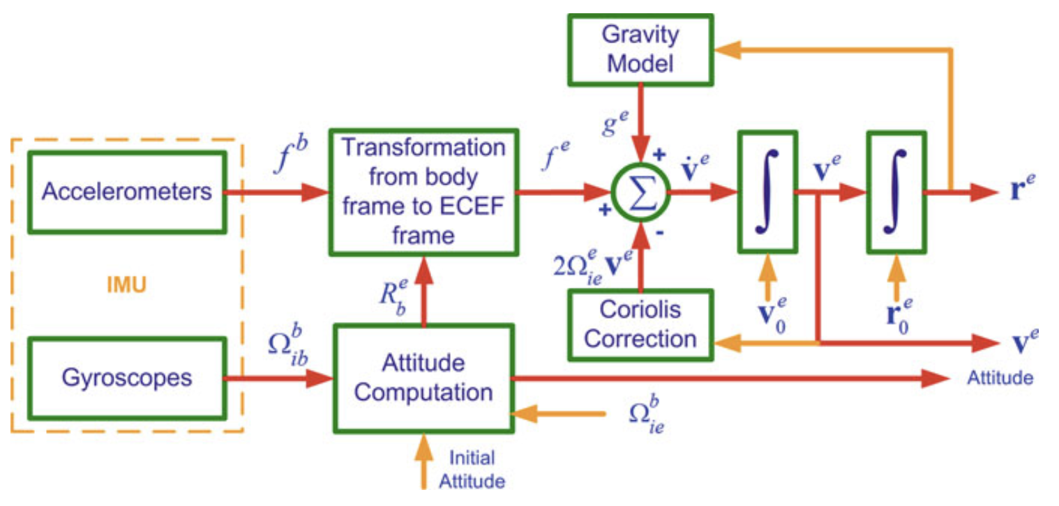
A note on the difference in which frame the angular velocity is expressed in
- Related to Rotation Matrix Time Derivative
- If is expressed in the inertial/fixed frame:
- If is expressed in the rotating/body frame:
Mathematical Proof (From the book):
A position vector in the in the e-frame can be transformed into the i-frame by using the Rotation Matrix as follows:
After differentiating twice and rearranging the terms (see here) we get:
But we know that , therefore , so:
This can be simplified by letting and , because the Earth’s rotation rate is approximately constant.
and because the gravity vector is defined as (true gravitational acceleration - centrifugal acceleration due to Earth’s rotation), this can be further reduced to:
which is equivalent to
q.e.d.
The rate of change of the rotation matrix can be given as
To extract , we can do the following chain rule:
Substituting, we get:
So the e-frame mechanization equations can be summarized as:
The term in the velocity derivative comes from the rotation of the Earth.
INS Mechanization in Local-Level (Navigation) Frame
In many applications the mechanization equations are desired in the local frame for the following reasons:
- The navigation equations in the l-frame furnish a navigation solution that is intuitive to the user on or near the Earth’s surface.
- Since the axes of the l-frame are aligned to the local east, north and up directions, the attitude angles (pitch, roll and azimuth) can be obtained directly at the output of the mechanization equations when solved in the local-level frame.
- The computational errors in the navigation parameters on the horizontal (E-N) plane are bound by the Schuler effect
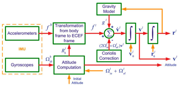
The position vector of a moving platform expressed in the geodetic (curvilinear) coordinates in the ECEF frames as:
The rate of change of its position is expressed in terms of the velocity in the east, north and up directions. The rate of change of the platform’s latitude, longitude and altitude are
- is the component of the velocity in the east direction
- is the component of the velocity in the north direction
- is the component of the velocity in the up direction
- is the meridian radius of the ellipsoid
- is the normal radius of the ellipsoid
Thus, we can write
in which transforms the velocity vector from rectangular coordinates into curvilinear coordinates in the ECEF frame.
Calculation of the velocity derivative:
The Earth-referenced velocity vector can be transformed into the local-level frame by using the rotation matrix
where . The time derivative is therefore:
We substitute for , where is the skew-symmetric matrix corresponding to
and since and :
We can transform the position vector r from the ECEF frame into the inertial frame by . Taking the time derivative and using the relationship gives:
where is the skew-symmetric matrix corresponding to .
After a lot of mathematics and simplifications, we get to the final local-frame mechanization equations:
with
Dead Reckoning: the process of calculating one's current position by using a previously determined position, or fix, by using estimations of speed and course over elapsed time
This sounds like drift errors.
Mechanization (Attitude)
- Attitude is independent of position and velocity.
- Position and velocity depend on attitude.
- IMU output: angular rate of body frame wr.t. inertial frame
- Desired output: angular increment of body frame w.r.t. local-level frame
- It’s a first order differential equation
Mathematical Foundation:
where is the Rotation of the Earth and is the ellipsoid model for the geographical coordinate system.
We know that and that where N and M are the radius of curvature of the prime vertical and meridian ().
In the end, we can extract the desired output based on (IMU’s output w.r.t. the inertial frame — measured) and (Earth’s rotation w.r.t. the inertial frame — known)
Mechanization of Velocity in Navigation Frame
The change of velocity in local-level frame where and :
Mechanization (Position)
What happens at the North pole?
- The equation diverges as goes to zero! That’s why we create a Wander Frame where the z-vector is pointing elsewhere than at the North pole.
Data Smoothing
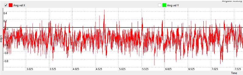
- INS rely on accelerometer and gyroscope data for estimating position, velocity, and orientation
- Data Smoothing reduces noise and thus improves the reliability of navigation solutions
Sliding Window Averaging:
- Applies a moving average over recent measurements
- Reduces short-term fluctuations while preserving trends
- Velocity is calculated for example by using modified Euler formula
Kalman Filtering:
- Optimal estimation combining sensor data and system dynamics
- Correct for drift and noise by incorporating external measurements like GPS
Complementary Filtering:
- Combined high-freq data (gyroscopes) and low-freq data (accelerometers)
- Simple and computationally efficient
- Can be used e.g. for gyro bias estimation
What if one directly uses the IMU measurements to integrate attitude? That is, by assuming that Earth's rotation is negligible with the following assumption:
Answer: There will be an accumulating drift on the angle! The magnitude of this drift follows from Earth’s rotation. When integration time is less than 1s, the effect could be negligible but if integration is continued even with these small steps, the error accumulates with respect to time
Per short: That exact amount we consider 0 () will be the error accumulating in our data.
Introduction to Rodrigues’ Formula
Lie Algebra
Covered in Lie Algebra.
As a general idea, we represent a spatial rotation SO(3) by an axis-angle pair. This way, we represent every rotation as a single operation instead of 3 in the case of Euler Angles.
where u is the rotation axis and is the rotation magnitude.
The associated element of the lie algebra is the skew-symmetric matrix denoted as
The exponential map provides the correspondence
linking the axis-angle (lie algebra) representation with a rotation matrix
Closed form exponential of a skew-symmetric matrix
For any matrix , the exponential is defined by
When , its powers satisfy
Starting from
use
Odd powers are proportional to :
Even powers are proportional to :
Using these identities, the series can be summed in closed form:
This expression is known as Rodrigues’ Rotation Formula.